
Design Patterns for Increased Security in Industrial Networks
Gone are the days when industrial networks could be physically separated from all other networks. The same applies to the myth of security through incompatibility, which has long given industrial plants a feeling of security.
Times have changed, and not solely because of developments such as the industrial Internet of Things and Industry 4.0, which have resulted in greater interconnectedness and homogenization of industrial plant network structures. Industrial component manufacturers have already started designing their connectable components based on standard industrial PC systems.
They are also increasingly replacing proprietary communication protocols with the network protocols Ethernet and TCP/IP, which are widely used and accepted worldwide. However, this enhanced networking means that industrial plants have a larger attack surface.
What’s more, many monitoring and control systems are used for years, sometimes decades at a time without receiving or being able to receive security updates in a timely manner. Either such patches are unavailable or a change in software is not without risks or may invalidate existing certifications.
This results in numerous soft targets in an application with industrial control systems. It is evident, therefore, that these important but vulnerable systems must be protected. Many companies set up perimeter firewalls at the edge of their industrial networks to protect the soft targets in their industrial applications against threats from the Internet or from office networks. Although this is a necessary step, modern network security demands far more than just perimeter security.
Comprehensive network security concepts need to take into account both different methods of attack and different kinds of attackers. This includes scenarios where the first line of defense has already been compromised, i.e., the firewall at the edge between the production network and the office network or the Internet. Once an attacker has penetrated a network, they can quickly cause major damage if the architecture and configuration if the network were selected with no regard for security. The good news: Implementing a network capable of withstanding an invading
attacker is not as complicated as it may first appear, provided security is taken into account as early as the network planning stage.
Zones and Conduits as a Basis for Secure Industrial Networks
When designing networks, the network infrastructure may be based on a range of architecture patterns. The choice of pattern has a strong bearing on the security of the network and makes all the difference between an easily attackable network and a resistant network. Given that architecture and topology are the basic pillars of a secure network, industrial security standards – such as the ISO/IEC 62443 family of standards – have been laid down for network design to show plant operators and system integrators how to create more effective network structures.
One of the most important network design guidelines is the principle of “zones and conduits”. Under this principle, an industrial network is segmented into different functional zones and the connections between these zones (i.e., the conduits)
relay only permitted data traffic from one zone to another zone. For example, a machine or part of a machine might represent a zone, within which various devices need to and are able to communicate with each other without restriction. Conversely, very few devices need to communicate with devices in other zones. An example of this would be a log server, which collects event logs from all the systems in the network. The server should be reachable across zone boundaries from different zones. Detailed rules should also be laid down at zone transitions specifying which traffic is permitted to leave the zone (e.g. traffic to the log server) and which traffic should not be relayed across zone boundaries (e.g. all traffic not directed to the log server).
Several things need to be taken into account when implementing zones and conduits. On the one hand technical measures need to be put in place to control the zone transition. In most cases firewalls and access control lists (ACLs) will be the most appropriate method. Figure 1 shows a simple industrial application divided into various functional zones.
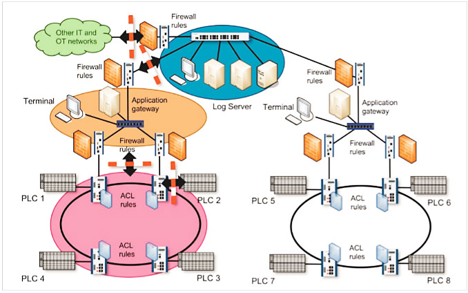
Figure 1: Various zones in an industrial application
The figure illustrates how firewalls with restrictive rule sets reduce traffic between the zones. Within a zone, Ethernet switches with ACLs also restrict traffic from and to devices. As well as dividing a network into zones, access to the individual zones needs to be protected. Technologies such as IEEE 802.1X in combination with an authentication protocol such as RADIUS are particularly suitable for this purpose. Finally, care must be taken to ensure that within the zones, too, attackers are unable to disrupt or manipulate network operations (e.g., through spoofing attacks). The following sections will go into these three issues in more detail.
Using Firewalls and Access Control Lists to Divide a Network into Zones and Conduits
A network can be segmented into zones by configuring packet filtering rules at various layers of the ISO/OSI layer model on switches, through firewalls or through application level gateways (ALGs). Since ACLs have a similar function to stateless firewalls and ALGs need to be adapted for special applications, the following section will focus in particular on firewalls that can be put to use flexibly. Firewalls and ACLs block unauthorized traffic by filtering traffic based on connection metadata (e.g., MAC addresses, IP addresses, port numbers and protocol flags).
According to the whitelisting principle (only known data traffic is allowed through while all other traffic is blocked), a firewall‘s rule sets only contain the properties of known and desired traffic. In the example above, all traffic moving beyond zone perimeters that is not directed to the log server can be rejected. It is therefore not possible to communicate with other devices outside the zone via the zone perimeter (the conduits). Whitelisting limits the extent to which attackers can have an influence beyond a zone perimeter because they make it difficult or even impossible for them to communicate with potential targets via the conduits.
To enable a firewall to be configured in the most restrictive way possible, care must be taken when designing the
network infrastructure to ensure that the network is divided into sensible zones. The zones should be as small as possible but at the same time, as little communication as possible should take place over zone perimeters. There are various design patterns (patterns and anti-patterns) in the IT world that are better or worse suited for dividing up a network. These patterns can either strengthen or weaken system security.
Patterns and Anti-patterns in Networks with Firewalls
Firewalls may be configured at various points on a network. Where they are positioned often determines whether a firewall-protected system can effectively shield against a threat to plants at a given location. The whitelisting principle mentioned above is a good pattern for later creating firewall rule sets.
The corresponding counter-model is blacklisting, which allows all unknown data traffic through and only blocks traffic known to be insecure. Besides the models used to set firewall rules there are also general models for mapping out the topology or structure of a network. The two main anti-patterns that need to be taken into account are the “flat network” and “screened host” anti-patterns. The “screened subnet” firewall pattern is a considerably more effective model.
The first anti-pattern for mapping out a network topology is the “flat network” design pattern. This kind of topology arises when security aspects are not taken into account in the design phase of the network. A network with a flat topology connects all devices regardless of their function and risk potential. Thus, one large zone is created that contains all devices. The obvious “advantage” of this pattern is that the structure is functionally suitable for all networks as there are no restrictions on the connections between any of the devices.
The disadvantage of this pattern is the complete loss of control over possible communication in the network. Since every device in the network can communicate with any other device in the network, all an attacker needs to do is compromise one device within a “flat network” to establish a connection to all the devices in that network. For this reason, special protection cannot be given to soft targets (i.e., potentially vulnerable devices) or business-critical devices. Despite the fact that this pattern is clearly unsuitable for preventing attackers from accessing other parts of the network (and thereby penetrating the whole network), it sadly still remains widespread in many industrial plants. If the implementation of zones and conduits to protect against the “flat network” anti-pattern is too simply thought-out, this can often lead to the second risky design pattern: the “screenedhost” anti-pattern. When a firewall is used to divide up a network into multiple zones, there must be a possibility that a particular communication will be able to flow between the zones through the firewalls. This is often due to services that devices (hosts) offer to other hosts in other zones.
An example of this might be the log server mentioned above. Let’s assume that the task of a server is to consolidate the protocol data from all devices in a plant in order to provide a complete picture of all events at the plant.
Figure 2 shows this scenario.
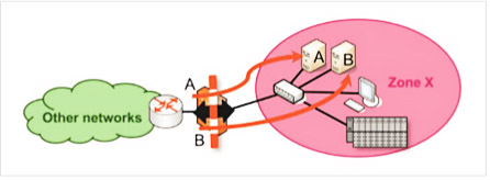
Figure 2: “Screened host” counter-model
The protocol server (host A) needs to be reachable outside its zone (zone X). To make this possible the network administrator can punch a hole in the firewall (add a permissive rule) so that devices outside zone X can now reach the server (host A). Perhaps there is also an additional service B that needs to be reachable from outside zone X. To make this service available, a further hole is punched in the firewall by opening the communication protocols and communication endpoints for this additional service in the firewall.
In theory, the firewall then permits access to A and B from other zones while simultaneously protecting the other devices (the terminal and controller in zone X) from attackers. In practice, however, an attacker could still exploit a software vulnerability in services A and B in order to take over protocol server A or host B. In this case the attacker would then have a foothold in zone X and would be able to access the services of the terminal or controller to inflict damage. The problem with the “screened host” architecture model is that zone X contains both reachable and compromised services (A and B) and other services which should not be reachable. The solution to this problem is to separate compromised services A and B from the other devices in zone X by implementing the “screened subnet” architecture model.
It is good practice in IT security to isolate exposed and potentially more vulnerable services into separate zones. These zones are generally designated as demilitarized zones (DMZ) and contain services like web servers, DNS servers and email servers. Typically these zones are often found at the perimeter of the company network, i.e., at the gateway to the Internet. This model is known as the “screened subnet” architecture model.
Figure 3 shows this model. Services A and B are isolated in zone Y but are also reachable from zone X and from other zones of the plant. However, services A and B are prohibited from communicating with the devices in zone X.
Even if an attacker is able to penetrate the exposed services in the DMZ, the programmable logic controller (PLC) and terminal in zone X remain protected by the firewall. The implementation of the “screened subnet” pattern requires a firewall that supports multiple ports for multiple zones, or two different firewalls between the DMZ and the rest of the network, as depicted in Figure 3. However, the improved security justifies the additional expenditure in almost every case.
Controlling Access to a Zone
A further factor determining the effectiveness of a security concept featuring zones and conduits is the security of access to the zones. Even the most restrictive firewall at the perimeter of a critical network component will be useless if an attacker is able to connect directly to a sensitive zone by just plugging in a device into a switch. To restrict zone access to authorized devices only, protections can be put in place in the form of both physical mechanisms and protocols. The physical protection of network equipment should always form the basis of any kind of network security. Network devices such as switches, firewalls, WLAN access points, etc., should be stored in locked cabinets so that unauthorized parties are unable to insert, remove or reconnect cables in order to gain access to the network or prevent other devices from accessing the network.
Physical protection is also necessary in order to ensure a basic degree of protection for the availability of network
communications in general. If an attacker succeeds in cutting power to a device, resetting its configuration or having an otherwise negative impact on the device, the network can be severely disrupted. It may sound mundane, but physically separating the attacker from all devices protects a network against many kinds of attackers and methods of attack. Likewise, having network devices that are not freely accessible significantly reduces the risk of unintentional or negligent network interference. Network devices cannot always be physically protected and physical protection does not always provide an adequate level of security. Consider for example devices which, due to a lack of space, are stored in an open area or in unlocked cabinets together with other devices that need to be accessible. By the same token, attempting to restrict access to wireless systems by implementing physical measures is extremely difficult and unreliable – after all, the microwaves emitted by WLAN systems are also able to penetrate walls and ceilings, quite the intention to a certain degree. Protocols therefore need to be implemented which can identify and authenticate the participating network devices in order to control access to the network.
Simple techniques such as limiting network communication to individual device identifiers like MAC addresses and IP addresses are relatively easy for attackers to bypass. In order to properly restrict network access, strong passwords or public key authentication mechanisms should be used as a form of protection. IEEE 802.1X is now.
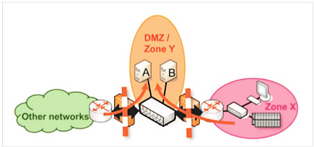
Figure 3: “Screened subnet” architecture model
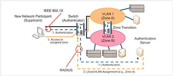
Figure 4: Authentication of a new network node using IEEE 802.1X with subsequent allocation to a zone
The de-facto standard for both wireless (IEEE 802.11 WLAN) and wired (IEEE 802.3 Ethernet) connections in combination with an authentication server (e.g., RADIUS). Under IEEE 802.1X, every network client (e.g., a component or machine) has clear and unique access data (e.g., username and password or a digital certificate) which it uses to identify itself to the switch or WLAN access point to which it is connected. When a new client logs onto the network, the switch or WLAN access point sends notification messages to an authentication server. The server then compares the access data with its user database and instructs the switch to either allow or block the connection by the new network client. Figure 4 shows such a connection by a new device.
From a security standpoint using IEEE 802.1X in combination with an authentication server offers two key advantages:
- Every device can be assigned different access credentials. As such, access to the network can be controlled on a per-device basis because the devices can be distinguished by their access credentials. What‘s more, if a device is stolen or lost, only that device needs to be removed from the network. The device simply needs to be centrally blocked on the authentication server. It is no longer necessary to reconfigure other devices in the network (e.g., firewalls or other WLAN clients with the same WLAN key) as the access is blocked specifically for this device.
- As well as controlling access to the network, the device can be allocated to a zone in the form of a virtual LAN (VLAN). Only devices in the same VLAN are able to communicate with one another. The transitions between the zones, which can be dynamically allocated by way of VLANs, can then be restored using firewalls.
These advantages allow network device access to be controlled using IEEE 802.1X, a network to be efficiently distributed into zones, and devices to be allocated to the right zones. By configuring device allocations centrally on the authentication server, making changes to zone membership and network access can be made in a very efficient way by just altering the authorization information on the server.
Additional Protection within a Zone
Besides the protection of zone boundaries and protecting access to individual zones, it is also important that devices within the zone are unable to impersonate other devices. This assumption of a false identify in the network is known as “spoofing”. This becomes extremely important when an attacker has access to a device that is already in a zone and
wants to gain access to other devices or zones or disrupt communication within the zone by assuming false identities. Spoofing can take place on various network layers, take on various identities and have extremely different effects. In the case of ARP spoofing, a device announces another devices‘ IP address under its own MAC address in the Ethernet network. In the case of DHCP and DNS spoofing, an attacker responds to device requests with forged information.
These attacks can result in data traffic being redirected to the attacker, allowing the attacker to have an influence on how other devices communicate. In their default configuration Ethernet networks are largely deployed without protection against such attacks. However, with techniques such as port security and Dynamic ARP Inspection, as well as IP Source Guard and DHCP snooping, there are effective security mechanisms available to help prevent spoofing attacks. These methods are also available in high-quality industry switches and can be used to severely restrict an attacker’s influence on the local network. What is important, however, is that these techniques require a configuration that is customized to the network and therefore that all switches are not activated by default. Additional protection can thus only be achieved following activation.
Summary and Conclusions
Taking security into account during the initial phase of network design is an important step towards creating a more secure industrial control system. However, issues such as exposed services must also be incorporated as a matter of principle, e.g., by enforcing best practices such as the implementation of firewalls and the zones and conduits concept. Disregarding the “flat network” architecture design and the “screened host” design in favor of the “screened subnet” architecture limits an attacker‘s freedom of movement within a network and better protects critical
or vulnerable devices against compromised services. When it comes to restricting device access to the network and allocating devices to individual zones, IEEE 802.1X represents an effective way to increase security and reduce the administrative burden. Finally, there are other ways of strongly limiting the influence an attacker can have within a zone. Using these methods and architectures helps to create secure and robust networks. Consequently, the network can no longer be used by the attacker as a dangerous weapon but instead acts as a serious barrier to attacks in industrial environments.
Prof. Dr. Tobias Heer – CTO Office, Hirschmann Automation and Control GmbH
Dr. Lars Geiger – Manager Advance Development, Hirschmann Automation and Control GmbH